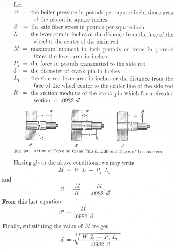
In A, K, and C, Fig. 90, is shown the manner in which the forces act on the crank pins of three-Sifterent types of locomotives.
This equation may be used in finding the diameter of the main crank pin on any type of locomotive when the loads and lever arms are known and the safe fiber stress has been assumed. It should be remembered, however, that for an 8-wheeled locomotive it is
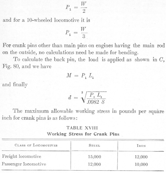
In addition to figuring the crank pins for bending, the bearing surface must be given some attention. In order to prevent overheating and to secure the best results, the pin must be designed so that the unit pressure will not exceed an amount determined by past experience. This allowable pressure in practice varies from 1,600 to 1,700 pounds per square inch of projected area, the projected area being the diameter of the pin multiplied by its length. It often happens that it is necessary to make the pin larger than is required for safe strength in order that the allowable bearing pressure may not be exceeded.
