LOCOMOTIVE APPLIANCES In order to enable the engineer to operate and control a locomotive successfully and economically a certain number of fittings on the locomotive are necessary. These fittings consist chiefly of the safety valves, whistle, steam gauge, lubricator, water gauges, blower, throttle valve, injector, air brake, and signal apparatus.
Safety Valves. The universal practice at present is to use at least two safety valves of the pop type upon every locomotive boiler. On small locomotives where clearances will permit, the safety valves are placed in the dome cap. On large locomotives where the available height of the dome is limited, the safety valves are usually placed on a separate turret. When limiting heights will not permit the use of turrets, the safety valves may be screwed directly into the roof of the boiler.
The construction of a good safety valve is such that when it is raised, the area for the escape of steam is sufficient to allow it to escape as rapidly as it is formed, and that as soon as the pressure has fallen a pre-determined amount, it will close.
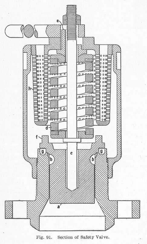
It should be so designed that it can neither be tampered with nor get out of order. It must act promptly and efficiently and not be affected by the motion of the locomotive. These conditions are all fulfilled in the type of valve shown in section in Fig. 91. In this design, the valve a rests on the seat b b and is held down by a spindle c, the lower end of which rests on the bottom of a hole in the valve a. A helical spring d tests on a collar on the spindle. The pressure on the spindle is regulated by screwing the collar e up or down. The valve seat b b may be rounded or straight. Outside of the valve seat there is a projection f, beneath which a groove g is cut in the casing. When the valve lifts, this groove is filled with steam which presses against that portion of the valve outside of the seat, and, by thus increasing the effective area of the valve, causes it to rise higher and to remain open longer than it otherwise would without this projection. The adjustment of the valve is usually made so that after opening, it will permit steam to escape until the pressure in the boiler is about 4 pounds below the normal pressure. The steam escaping through the small holes h, is muffled, thus avoiding great annoyance.
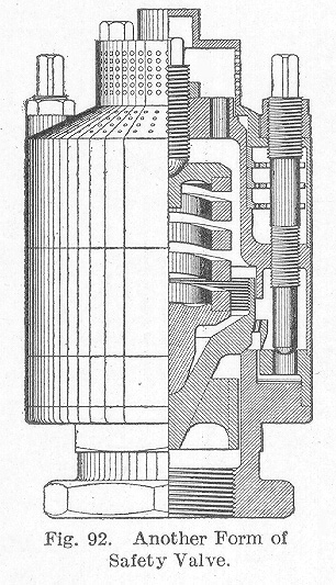
Another form of safety valve which is being largely used is that shown in Fig. 92. The principle of its operation is the same as that just described. It is said to be very quiet and yet gives effective relief. It is being adopted by several railroads.
Table of Contents; Page 135; Page 140; Index
