The Whistle. The whistle is used for signaling purposes and consists of a thin circular bell, Fig. 94, closed at the top and sharp at the lower edge. Steam is allowed to escape from a narrow circular orifice directly beneath the edge of the bell. A part of the escaping steam enters the interior of the bell and sets up vibrations therein. The more rapid these vibrations, the higher the tone of the whistle. The tone is affected by the size of the bell and the pressure of the steam. The larger the bell, the lower will be the tone. The higher the steam pressure, the higher the tone. In order to avoid the shrill noise of the common whistle, chime whistles are commonly used, one type of which is illustrated in Fig. 94. In this illustration the bell is divided into three compartments of such proportions that the tones harmonize and give an agreeable chord.Steam Gauges. The usual construction of the steam gauge will not be presented here but reference is made to the instruction paper on "Boiler Accessories."
Water Gauges. Water gauges are also fully explained in the instruction paper on "Boiler Accessories."
The Blower. The blower consists merely of a steam pipe leading from and fitted with a valve in the cab to the stack where it is turned upward. The end of this pipe is formed into a nozzle. The escaping steam gives motion to the air exactly as already explained for the exhaust and thus induces a draft through the fire-box. It is used when the fire is to be forced while the engine is standing.
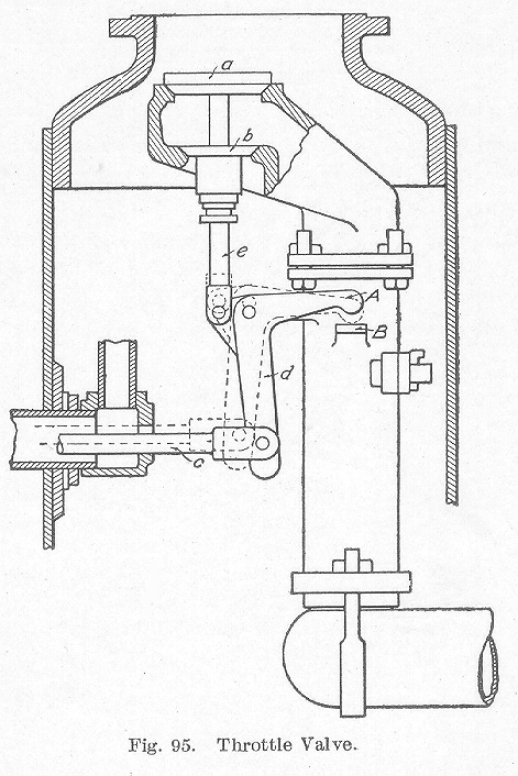
Throttle Valve. The throttle valve now in universal use is some form of a double-seated poppet valve, as illustrated in Fig. 95. In this type, two valves a and b are attached to a single stem, the upper valve being slightly the larger. The lower valve b is of such a diameter that it will just pass through the seat of the valve a. The steam, therefore, exerts a pressure on the lower face of b and the upper face of a. As the area of a is the greater, the resultant tendency is to hold the valve closed. The valve is, therefore, partially balanced. It will be difficult to open large throttle valves such as are now used on locomotives carrying high steam pressures, with the ordinary direct form of leverage. In such cases, it will be necessary to give a strong, quick jerk to the throttle lever before the valve can be moved from its seat. The arrangement of leverage shown in Fig. 95 obviates this difficulty. The rod c connects with a lever in the cab and coauxuliucates its movement to the bell crank d, whence it is carried by the stem e to the valve. The pivot of the bell crank is provided with a slotted hole. At the start, the length of the short arm is about 2¼ inches while the long arm is about 9½ inches. After the valve has been lifted from its seat and is free from excess pressure on a, the projecting arm A on the back of the bell crank comes in contact with the bracket B on the side of the throttle pipe and the bell crank takes the position shown by the dotted lines in the figure. The end of the projecting arm A then becomes the pivot and the length of the short arm of the lever is changed to 9½ inches and that of the long arm to about 11½ inches.
Table of Contents; Page 140; Page 145; Index
