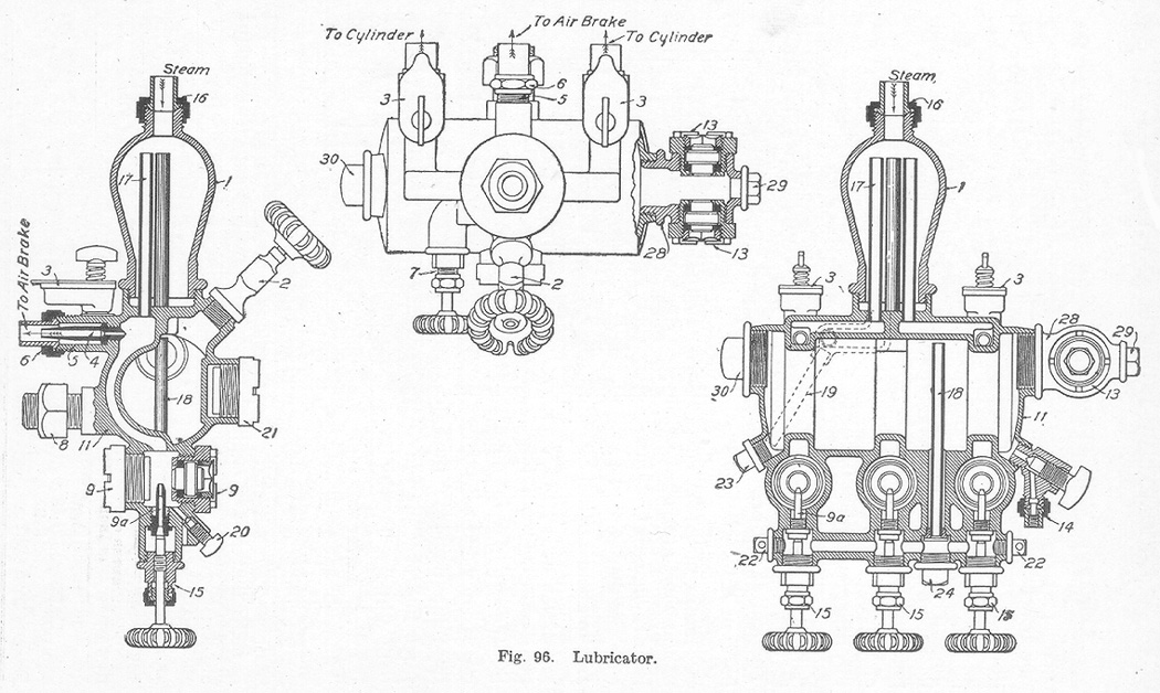
Lubricator. The lubricator, one of the most essential locomotive appliances, is usually supported by a bracket from the back head of the boiler in convenient reach of the engineer. It may be a two-, three-, or four-sight feed lubricator as the case demands, the number of sight feeds indicating the number of lubricating pipes supplied by the lubricator. For instance, a two-sight feed lubricator has two pipes, one leading to each steam chest. A triple-sight feed is used to supply oil to both steam chests and also to the cylinder of the air pump. In using superheaters, it has been found necessary to oil the cylinders as well as the valves, hence the need of the four-sight feed lubricator. Fig. 96 shows sections of a well-known make of a triple-sight feed lubricator. The names of the parts are as follows:
1. CONDENSER 15. REGULATING VALVES 2. FILLING PLUG 16. TOP CONNECTION 3. HAND OILER 17. EQUALIZING PIPE 4. CHOKE PLUG or REDUCING PLUG 18. OIL PIPE 5. TAILPIECE 19. WATER PIPE 6. DELIVERY NUT 20. SIGHT FEED DRAIN VALVE 7. WATER VALVE 21. EXTRA GLASS AND CASING 8. STUD NUT 22. CLEANING PLUG 9. SIGHT FEED GLASS AND CASING 23. BODY PLUG 9a. FEED NOZZLE 24. OIL PIPE PLUG 11. BODY 28. GAUGE GLASS BRACKET 13. GAUGE GLASS AND CASING 29. CLEANING PLUG 14. WASTE COCK 30. GAUGE GLASS CAP The lubricator is fastened to the boiler bracket by means of the stud nut, 8. In brief, the operation of the lubricator, as illustrated in Fig. 96, is as follows:
Steam is admitted to the condensing chamber, 1, through the boiler connection, 16. The steam condenses in the condenser and passes through the equalizing pipe to the bottom of the oil reservoir. The lubricator is filled at the filling plug, 2. As the condensed steam fills up the lubricator, the oil level is raised until the oil passes through the tubes, 18, to the regulating valve, 15, from whence it is permitted to pass drop by drop through the sight feed glass, 9, to the different conveying pipes. To fill the lubricator, first be sure that the steam valve is closed, then remove the filling plug and pour in the necessary amount of oil. After the filling plug has been replaced, open the steam valve slowly and let it remain open. After this, regulate the flow of oil by means of the regulating valves, 15.
Air Brake and Signal Equipment. The air brake and signal equipment are fully explained in the instruction book on the "Air Brake" and will not be presented.
Table of Contents; Page 145; Page 148; Index
