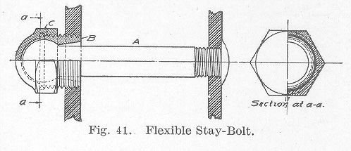
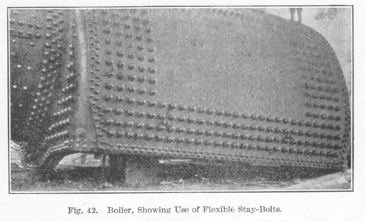
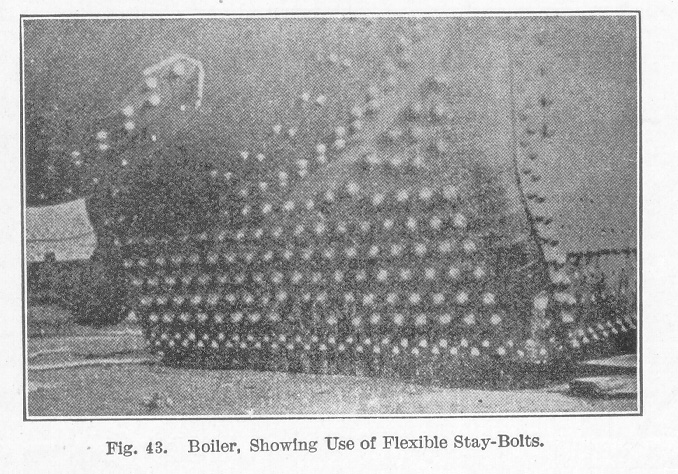
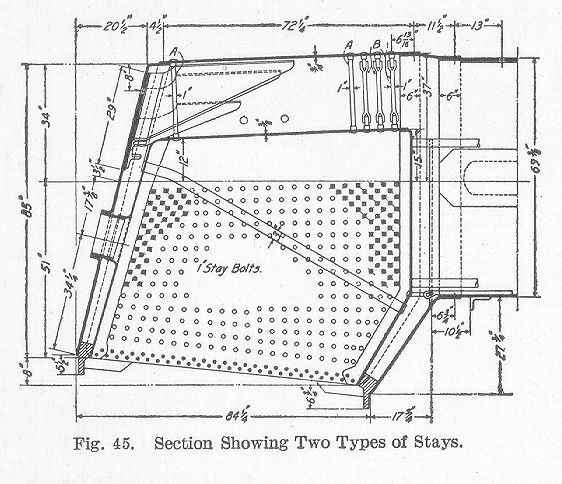
Stay-Bolts. The universal method of staying flat surfaces of the fire-box at the sides and front is by the use of stay-bolts. These stay-bolts are screwed through the two sheets of the fire-box and are riveted over on both ends. Fig. 40 illustrates a stay-bolt screwed into position and represents a strong and serviceable form. The stay-bolt is cut away between the sheets and only sufficient thread is cut at the ends to give it a hold in the metal. In Fig. 40, A represents the inside sheet or the one next to the fire, and B represents the outside sheet. A small hole C is drilled into the outside end of the stay- bolt. This is known as the tell-tale hole and will permit the escape of water and steam should the bolt become broken. This tell-tale hole is usually 3/16 of an inch in diameter and 1 1/4 inches deep and is drilled at the outer end of the stay-bolt, since almost invariably the fracture occurs near the outer sheet. All boiler stay-bolts, including radial stays, have 12 Whitworth standard threads per inch. The most common cause of stay-bolts breaking is the bending at the point B, Fig. 40, due to the expansion of the sheets A and B. The sheet A, being next to the fire, is kept at a much higher temperature while the boiler is at work than the sheet B, which is subjected to the comparatively cool temperature of the atmosphere. This causes the plates A and B to have a movement relative to each other due to unequal expansion. The breakage is greatest at points where the greatest amount of movement takes place. As the two sheets are rigidly fastened to the mud ring, it is evident that the variation of expansion must start from that point; hence, the greatest vertical variation will be found at the top of the fire-box. In like manner, the back heads are securely fastened by stay-bolts so that horizontal variation must start at the back end; consequently the greatest horizontal variation will be found at the front end of the fire-box. The result of these two expansions will, therefore, be greatest at the upper portion of the front end. It is there that the greatest number of staybolt breakages occur.Table of Contents; Page 43; Page 50; IndexIn order to avoid these bending stresses, a number of different forms of flexible stay-bolts have been designed. One form of these is shown in Fig. 41. The stay-bolt proper, A, has a ball formed on one end and a thread cut on the other. A plug B sets over the ball and forms a socket in which the latter can turn. As the stay- bolt is free to revolve in the plug, there is no necessity of the thread of the stay-bolt being cut in unison with the thread on the plug. Such a stay-bolt as this permits the inner sheet of the fire-box to move to and fro relative to the outer sheet without bending the outer end of the stay-bolt. Flexible stay-bolts when used are placed in what is known as the zone of fracture. Fig. 42 and Fig. 43 illustrate the application of flexible stay-bolts to a wide fire-box. Fig. 42 shows five rows of flexible stay-bolts at each end of the fire-box and four rows at the bottom parallel to the mud ring. It should be remembered, however, that this is one installation only and that the arrangement in all cases may vary but this illustration is representative of good practice. Another illustration is shown in Fig. 45. Here the flexible stay-bolts are shown by shaded circles. It is evident from Fig. 43 that all the stays in the throat sheet are flexible, which is a very good arrangement since the stay-bolts in the throat sheet are subjected to very severe strains. On some railroads, flexible stay-bolts are put in the fire-box door sheets but this practice varies in some details for different roads.
Stay-bolts should be made of the best quality double refined iron free from steel, having a tensile strength of not less than 48,000 pounds per square inch. The bars must be straight, smooth, free from cinder pits, blisters, seams, or other imperfections. The common practice is to use stay-bolts 7/8 or 1 inch in diameter spaced about 4 inches from center to center.
Stay-bolt breakage is very large in bad water districts and gives a great deal of trouble on most railroads. The stay-bolt problem, therefore, is a very important one.
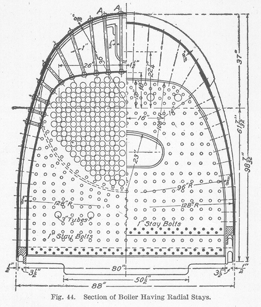
In addition to staying the sides and front and back ends, it is also necessary to stay the crown sheet. To accomplish this two general methods have been used. The oldest of these, by the use of crown bars, has almost passed out of service and well it is because of the many objectionable features it possessed. In this method, a number of crown bars were used which were supported by the edges of the side sheets and which were held apart by spacers resting upon the crown sheet and to which the crown bars were tied by bolts. The crown sheet was supported by stay-bolts which were bolted to the crown bars. A great deal of the space over the crown sheet was taken up by these crown bars which greatly interferred with the circulation and made it very difficult in cleaning. The second method of staying the crown sheet is by means of radial stays. All stay-bolts over 8 inches in length are usually classified as radial stays. Radial stay-bolts are of the same general type and material as the stay-bolts already described, and are put in on radial lines; hence their name. Fig. 44 shows a section of a boiler having radial stays A. These stays extend around the curved surface of the fire-box from the back to within two or three rows of the front end as illustrated at A, Fig. 45. The stays B in Fig. 45 are of a different form and are frequently used in the front end to allow for expansion and contraction of the flue sheet. These extend around to the curved surface in the same manner as do the radial stays shown in Fig. 44.
All radial stays should have enlarged ends with bodies 3/16 inch smaller in diameter than the outside diameter of thread. They should be made with button heads and should have threads under heads increased in diameter by giving the end a taper 1/2 inch in 12 inches. Radial stays commonly used are 1 inch, 1 1/8 inch, and 1 1/4 inch in diameter at the ends. The allowable safe fiber stress is 4,500 pounds per square inch.
