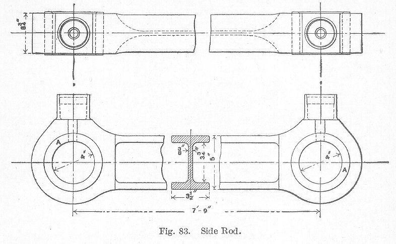
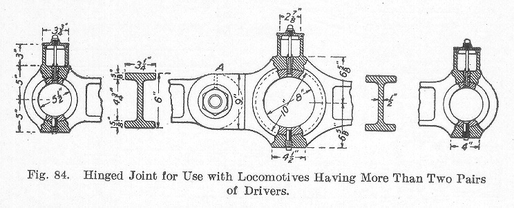
Connecting or Main Rods. Connecting or main rods are made of steel, the section of which is that of an I. The I-section gives the greatest strength with a minimum weight of metal. Fig. 82 illustrates modern practice in the design of connecting rods for a heavy locomotive. The design for passenger locomotives is quite similar to that shown. Aside from the general dimensions and weight of the rod, there are to be noted some important details in the manner in which the brasses are held and the means provided for adjusting them. The older forms of rods had a stub end at the crank pin end with a strap bolted to the rod. A key was used in adjusting the brasses. With the building of locomotives of greater capacity, this construction was found to be weak. The connecting rod shown in Fig. 82 has passed through several stages in the process of its development. The crank end is slotted, the brasses being fitted between the upper and lower jaw. The brasses are held in place by a heavy cotter A and a key B. The cotter is made in a form which prevents the spread of the jaws C and D. The adjustment of the brasses is made by means of the key B in the usual way. The brasses at the crosshead end are adjusted by the wedge E. The oil cups are forged solidly on the rod.The Parallel or Side Rods. The parallel or side rods are also made with an I-section in order to obtain a maximum strength with a minimum weight of metal. Fig. 83 illustrates the form of side rods now being used. The rods are forged out of steel, in the same manner as connecting rods, having oil cups also forged on. The enlarged ends are bored for the brasses which are made solid and forced in by hydraulic pressure. In case the locomotive is one having more than two pairs of drivers, the side rods are connected by means of a hinged joint as shown at A, Fig. 84.
Both connecting rods and side rods are subjected to very severe stresses. They must be capable of transmitting tensional, compressional, and bending stresses. These stresses are brought about by the thrust and pull on the piston and by centrifugal force.
Table of Contents; Page 112; Page 115; Index
