The pony truck, illustrated in Fig. 85, consists essentially of the two wheels and axle, the frame, 1, which carries the weight of the front end of the locomotive and the radius bar, 2, pivoted to the cross bar, 3, which is rigidly bolted to the engine frame, 4. The radius bars serve to steady the truck and reduce the flange wear on the wheels when running on curves. A side movement is provided for at the center plate, which is made necessary on account of curves. The correct length of the radius bar is given by the following formula:
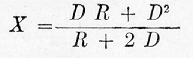
where
R = length of rigid wheel base of engine in feet
D = distance in feet from front flanged driver axle to center of truck
X = length in feet of radius bar
The usual method of applying the weight to a pony truck is by means of the equalizing lever, 5. The fulcrum, 6, of this equalizing lever is located under the cylinders where the weight is applied. The front end of the equalizing lever is carried by the pin, 8, which, in turn, is carried by the sleeve, 9, and transmits the load to the center plate while the rear end of the lever is supported by means of the cross lever, 10, which is carried by the driving wheel springs.
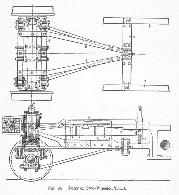
The four-wheeled truck is constructed in a number of different ways, one of which is illustrated in Fig. 86. The construction is simple, consisting of a rectangular frame, A, carrying a center plate, B. As in the case of the pony truck, the journals are inside of the wheels. The truck, which is pivoted on the center plate, carries the front-end of the locomotive and serves as a guide for the other wheels of the locomotive.
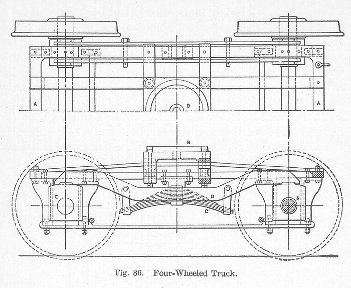
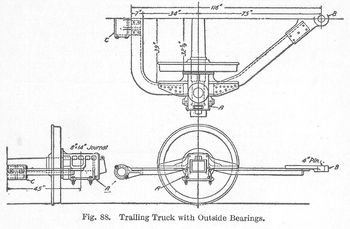
The object in using a trailing truck, as stated earlier in this work, is to make possible the wide fire box which is necessary in certain types of locomotives. Two different types of trailing trucks are used and both have proven successful. One has an inside bearing, as illustrated in Fig. 87, and the other an outside bearing, as shown in Fig. 88. The former is perhaps the simpler of the two. The latter has a broad supporting base which improves the riding qualities of the locomotive.
The radial trailing truck with inside bearings. Fig. 87, is fitted with a continuous axle box, A, with journal bearings at each end, these being provided at the frame pedestals with front and back wearing surfaces formed to arcs of concentric circles of suitable radii. To the lower face of the continuous axle box is attached a spring housing, B, fitted with transverse coiled springs having followers and fitted with horizontal thrust rods, C, which extend to the pedestal tie bars. These thrust bars terminate in ball and socket^connections at each end. This combination of springs and thrust rods permits the truck to travel in a circular path and also permits the continuous axle box to rise and fall relatively to the frames. Motion along the circular arcs is limited by stops at the central spring casing, the springs tending to bring the truck to its normal central position when the locomotive passes upon a tangent from a curve. The load is transmitted to the continuous axle box through cradles on which the springs and equalizers bear, hardened steel sliding plates being interposed as wearing surfaces immediately over the journal bearings. The cradles are guided vertically by guides attached to the locomotive frames.
The radial trailing truck with outside bearings, as illustrated in Fig. 88, has journal boxes A rigidly attached to the frame, the forward rails of which converge to a point in which the pivot pin B is centered. The pin is fixed in a cross brace secured between the engine frames. The trailing truck frame extends back of the journal boxes in the form of the letter U at the center of which a spring housing C is mounted, containing centering springs and followers, performing the same functions as those of the radial truck with inside bearings, already described. The load in this case is transmitted to the journal boxes by springs which are vertically guided. Hardened rollers are generally used between what would otherwise be sliding surfaces. These rollers rest upon double inclined planes which tend to draw the truck to its normal and central position when displaced laterally as on a curve. The mutual action of these rollers and inclined planes is to furnish a yielding resistance to lateral displacement with a tendency to return to the normal position.
