Compound Locomotive. In continuation of a study of the development of the various types of locomotives, it is important to consider the compound locomotive. The compound locomotive is one in which the steam is admitted to one cylinder, called the high-pressure cylinder, where it partially expands. From this cylinder the steam is exhausted into the steam chest of another cylinder having larger dimensions, called the low-pressure cylinder. From this steam chest, the steam enters the low-pressure cylinder where it continues its work and is exhausted into the atmosphere. There have been a large number of different types of compound locomotives developed, all of which have had more or less merit. The following types have been used in America: the four-cylinder balance compound, the Mallet compound, and the tandem compound. The remarks and description which follow, of the Cole four-cylinder compound, are quoted from publications of the American Locomotive Company, builders of this locomotive:The time has arrived when merely increasing weight and size of locomotives to meet increasing weights of trains and severity of service does not suffice. To increase capacity, improve economy, and at the same time reduce injury to track, a new development is needed. Limits of size and weights have been reached in Europe and to meet analogous conditions there, the four- cylinder balanced compound has been developed into remarkably successful practice. The purpose of the Cole four-cylinder balanced compound is to advance American practice by adapting to our conditions the principles which have brought such advantageous results abroad, especially the principles of the de Glehn compound.
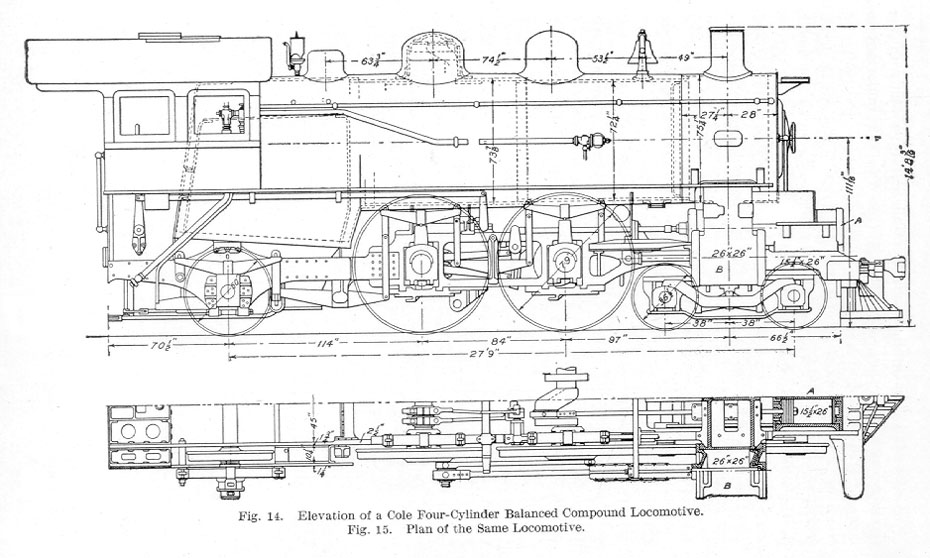
The Cole four-cylinder balanced compound employs the principle of subdivided power to the cylinders; the high pressure (between the frames) drives the forward or crank axle and the others; the low pressure (outside of the frames) drives the second driving axle. In order to secure a good length for connecting rods without lengthening the boiler, the high-pressure cylinders are located in advance of their usual position.
Special stress is laid on perfect balancing and the elimination of the usual unbalanced vertical component of the counterbalance stresses as a means for increasing the capacity, improving economy of operation and maintenance, and promoting good conditions of the track.
The relative positions of the high-pressure cylinder A and the low-pressure cylinder B may be seen in Fig. 14 and Fig. 15. The high-pressure guides, Fig. 15, are located under and attach to the low-pressure saddle, whereas the low-pressure guides are in the usual location outside of the frames The cranks of the driving wheels are 180 degrees apart. In order to equalize the weights of the pistons, those of the high-pressure cylinders are solid and those of the low-pressure cylinders are dished, and made as light as possible. A single valve motion, of the Stephenson type, operates a single valve stem on each side of the engine. Each valve stem carries two piston valves, one for the high- and the other for the low-pressure cylinder, as illustrated and explained later.
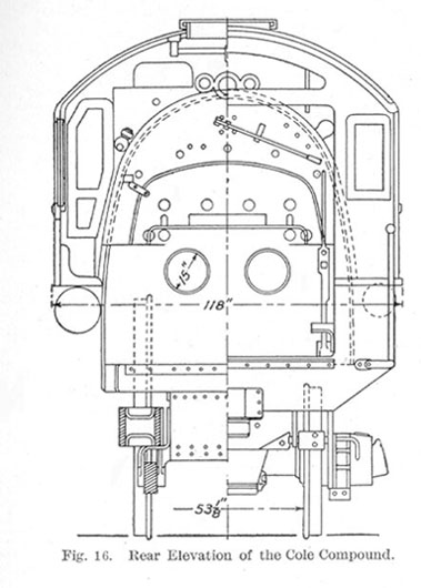
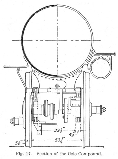
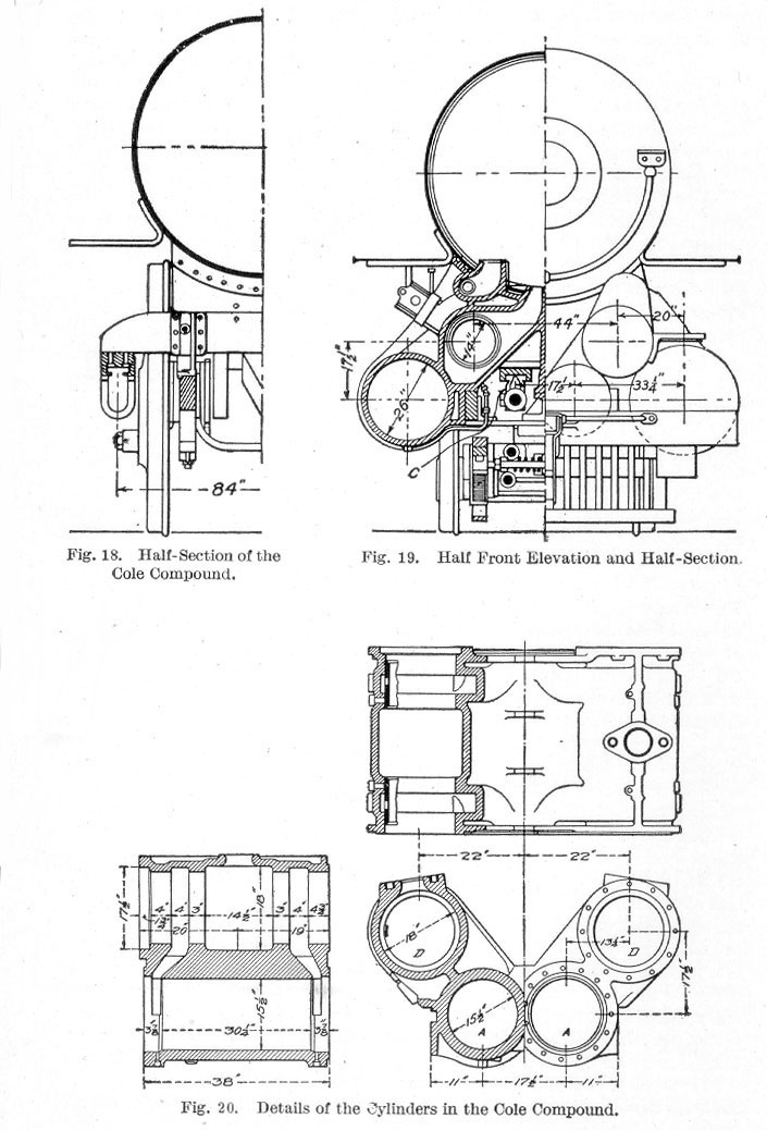
The back end, Fig. 16, and the two sections, Fig. 17 and Fig. 18, resemble ordinary construction of two-cylinder locomotives but the half front elevation and half section shown in Fig. 19 disclose a number of departures. The high-pressure piston rod, crosshead, and the guides C are shown in position under the low-pressure saddle. The high-pressure cylinders A and the high-pressure section of the piston valve chamber D are all in one casting, Fig. 20. The sides of the cylinder casting are faced off to the exact distance between the front plate extension of the frames. The valve chambers are in exact line with the valve chambers of the low-pressure cylinder; intermediate thimble castings and packing glands being inserted between the two, form a continuous valve chamber common to both high- and low-pressure cylinders, thus providing for expansion.
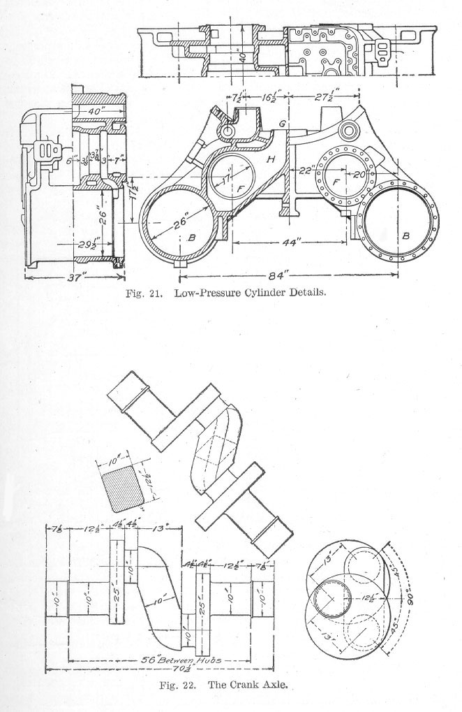
Fig. 21 shows the low-pressure cylinders B which are cast separately and bolted together. In this case the inside of the cylinders are faced off to proper dimensions to embrace the outer faces of the bar frame. The low-pressure piston valve chamber F is in direct line between the cylinder and the exhaust base G. This view illustrates the short direct exhaust passage H from the low-pressure cylinders to the exhaust nozzle.
Fig. 22, the crank axle, shows that under the existing conditions it is possible to make this part exceedingly strong. Inasmuch as the cranks on this axle are 90 degrees from one another, it is possible to introduce exceedingly strong 10 by 12½ inch rectangular sections connecting the two crank pins. The whole forms an exceedingly strong and durable arrangement constructed in accordance with the best European practice which is likely both to wear and stand up well in service. A cross-section of the central portion of the axle indicates its proportions between the crank pins.
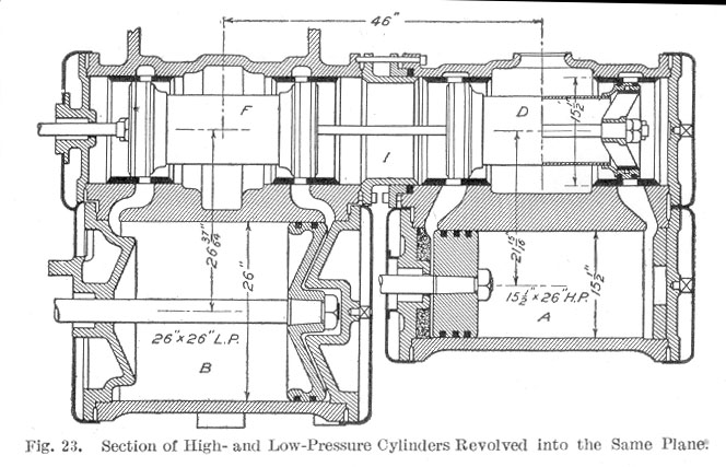
The high- and low-pressure cylinders, A and B, are shown in Fig. 23 as they would appear in section revolved into the same plane. The high-pressure valve D is arranged for central admission and the low-pressure valve F for central exhaust, both valves being hollow. A thimble casting or round joint ring and a gland connect the two parts of the continuous valve chamber I.
The following advantages of the four-cylinder balanced compound are claimed by the maker:
- The approximately perfect balance of the reciprocating parts combined with the perfect balance of the revolving masses.
- The permissible increase of weight on the driving wheels on account of the complete elimination of the hammer blow.
- An increase in sustained horse-power at high speeds without modification of the boiler.
- Economy of fuel and water.
- The subdivision of power between the four cylinders and between the two axles, and the reduction of bending stress on the crank axle due to piston thrust because of this division of power.
- The advantage of light moving parts which render them easily handled and which will minimize wear and repairs.
- Simplicity of design One set of valve gears with comparatively few parts when compared with other designs which have duplicate sets of value gears for similar locomotives.
Table of Contents; Page 13; Page 27; Index
