Another type of compound which is remarkable in many respects and which has had very successful usage in Europe is the Mallet articulated compound. It has been known and used in certain mountainous sections of Europe for several years but has recently been modified and adapted to meet American requirements. It is practically two separate locomotives combined in one, and advantage is taken of this opportunity to introduce the compound principles under the most favorable conditions. The following is a description together with dimensions of a large locomotive of this type built by the American Locomotive Company. Its enormous size is realized from Fig. 24 and Fig. 25. The weight of this particular locomotive in working order is nearly 335,000 pounds and the flues are 21 feet long. The rear three pairs of drivers are carried in frames rigidly attached to the boiler. To these frames, and to the boiler as well, are attached the high-pressure cylinders. The forward three pairs of drivers, however, are carried in frames which are not rigidly connected to the barrel of the boiler but which are in fact a truck. This truck swivels radially from a center pin located in advance of the high-pressure cylinder saddles. The weight of the forward end of the boiler is transmitted to the forward truck through the medium of side bearings, illustrated in Fig. 24, between the second and third pair of drivers. In order to secure the proper distribution of weight, the back ends of the front frames are connected by vertical bolts with the front ends of the rear frames. These bolts are so arranged that they have a universal motion, top and bottom, which permits of a certain amount of play between the front and rear frames when the locomotive is rounding a curve. The low-pressure cylinders are attached to the forward truck frames.
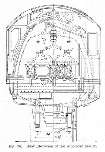
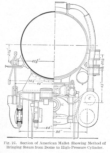
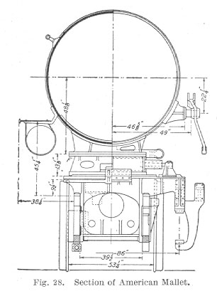
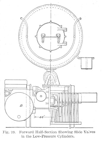
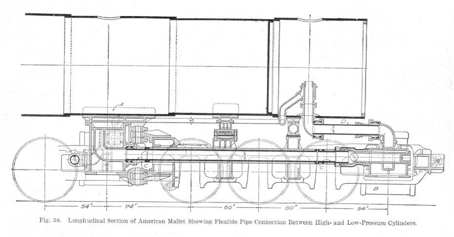
The steam dome is placed directly over the high-pressure cylinders A from which steam is conducted down the outside of the boiler on either side to the high-pressure valve chamber. The steam after being used in the high-pressure cylinders A passes to a jointed pipe C between the frames and is delivered to the low-pressure cylinders B, whence it is exhausted by a jointed pipe D through the stack in the usual way. The back end, Fig. 26, presents no unusual feature other than the great size of the boiler and fire-box. The section shown in Fig. 27 illustrates the method of bringing the steam down from the steam dome to the high-pressure valve E. The section in Fig. 28 clearly shows the sliding support F between the boiler and front truck. It also shows the method of attaching the lift shafts to the boiler barrel which is made necessary by the use of the Walschaert valve gear. Fig. 29 shows that the low-pressure cylinders B are fitted with slide valves, and also shows the jointed exhaust pipe from the low-pressure cylinder to the bottom of the smoke-box. Fig. 30 illustrates the construction and arrangement of the flexible pipe connection C between the high-pressure cylinder A and the low-pressure cylinder B. This pipe connection, as well as the exhaust connection D between the low-pressure cylinder and the smoke stack, serves as a receiver. The ball joints are ground in, the construction being such that the gland may be tightened without gripping the ball joint.
The builders claim for this design about the same advantages over the simple engine as were enumerated in the description of the Cole four-cylinder balanced compound. It is evident that the Mallet compound is a large unit and hence can deliver more power with the same effort of the crew. A reserve power of about 20 per cent above the normal capacity of the locomotive may be obtained by turning live steam into all four cylinders and running the locomotive simple which can be done at the will of the engineer when circumstances demand it.
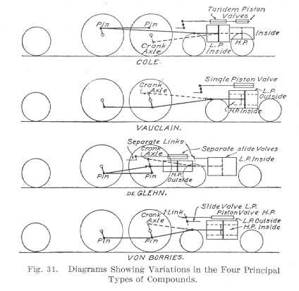
The diagrammatic illustration shown in Fig. 31 presents a good means of studying and comparing the four different types of compound locomotives referred to in the preceding pages. Briefly stated, the essentials in each of the four cases illustrated are as follows:
Cole. High-pressure cylinders, inside but in advance of the smoke-box, driving front axle. Low-pressure cylinders, outside in line with the smoke-box, driving rear driving axle. Two piston valves on a single stem serve the steam distribution for each pair of cylinders, and each valve stem is worked from an ordinary link motion.
Vauclain. High-pressure cylinders inside and low-pressure cylinders outside, all on the same horizontal plane, in line with the smokebox and all driving the front driving axle. As in the von Borries, a single piston valve worked from a single link effects the steam distribution for the pair of cylinders on each side.
De Glehn. High-pressure cylinders, outside and behind smoke-box, driving the rear drivers. Low-pressure cylinders, inside under smoke-box, driving crank axle of front drivers. Four separate slide valves and four Walschaert valve gears allowing independent regulation of the high- and low-pressure valves.
Von Borries. High-pressure cylinders inside and low-pressure cylinders outside all on the same horizontal plane in line with the smoke-box and all driving the front driving axle. Each cylinder has its own valve but the two valves of each pair of cylinders are worked from a single valve motion of a modified Walschaert type. This arrangement permits the varying of the cut-off of the two cylinders giving different ratios of expansion which cannot, however, be varied by the engine-man.
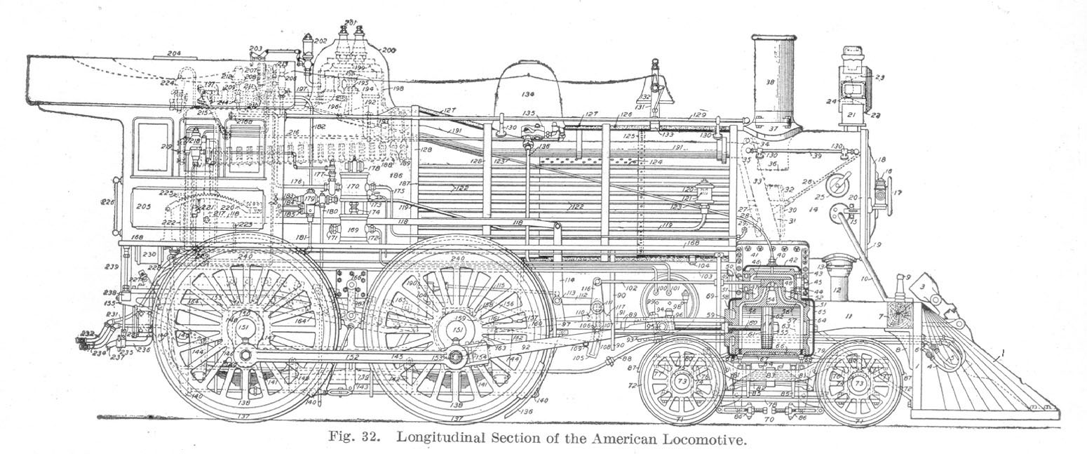
1-Pilot. 2-Draw Head Attachment. 3-Folding Draw Head. 4-Air Signal Hose. 5-Air Brake Hose. 6-Hose Hangers. 7-Buffer Beam. 8-Pilot Bracket. 9-Flagstaff. 10-Arch Brace. 11-Front Frame. 12-Cinder Chute. 13-Cinder Chute Slide. 14-Extension Front. 15-Headlight Front. 16-Signal Lamp. 17-Number Plate. 18-Smoke Arch Door. 19-Smoke Arch Front. 20-SmokeArch Ring. 21-Headlight Bracket. 22-Headlight Case. 23-Headlight Reflector, 24-Headlight Burner. 25-Cleaning Door. 26-Netting. 27-Deflector Plate. 28-Deflector Plate Adjuster. 29-Air Pump Exhaust Pipe. 30-Blower. 31-Nozzle Stand. 32-Nozzle Tip. 33-Steam Pipe (2). 34-T or Nigger Head. 38-Dry Pipe Joint. 36-Petticoat or Draft Pipe. 37-Stack Base. 38-Smoke Stack. 39-Arch Hand Kail. 40-Oil Pipe Plug. 41-Cylinder Saddle. 42-Steam Chest Casing Cover. 43-Steam Chest Cover. 44-Steam Chest. 45-Relief Valve. 46-Balance Plate. 47-Balanced Valve. 48-Valve Yoke. 49-Valve Stem. 50-Valve Stem Packing. 51-Steam Passages to Chest. 52-Valve Seat. 53-Bridges. 54-Exhaust Port. 55-Piston Rod Nut. 56-Steam Ports. 57-Cylinder. 58-Back Cylinder Head. 69-Piston Rod Packing. 60-Piston Rod. 61-Piston Head. 62-Piston Packing Rings. 63-Truck Center Castings. 64-Front Cylinder Head. 65-Cylinder Head Casing. 66-Cylinder Lagging. 67-Cylinder Casing. 68-Cylinder Cocks. 69-Cylinder Cock Rigging. 70-Engine Track Wheel. 71-Engine Truck. 72-Engine Truck Tire. 73-Engine Truck Axle. 74-Engine Truck Brass. 75-Engine Truck Box. 76-Engine Truck Pedestal. 77-Engine Truck Frame. 78-Engine Truck Pedestal Brace. 79-Engine Truck Frame Brace. 80-Engine Truck Equalizer. 81-Engine Truck Spring Hanger. 82-Engine Truck Spring. 83-Engine Truck Spring Band. 84-Engine Truck Spring Pocket. 85-Safety Hanger. 86-Truck Brake. 87-Wheel Guard. 88-Signal Pipe. 89-Guides. 90-Guide Yoke. 91-Guide Block. 92-Main Rod, 93-Main Rod Front Strap. 94-Key. 95-Crosshead Pin. 95-Crosshead. 97-Main Frame. 98-Air Drum Bracket. 99-Air Drum. 100-Pump Connection. 101-Train Pipe Connection. 102-Valve Stem Rod. 103-Train Pipe. 104-Wash Out Plugs. 105-Link. 106-Suspension Stud. 107-Link Block Pin. 108-Link Block. 109-Eccentric Connection, Back Up. 110-Eccentric Connection, Go Ahead. 111-Link Hanger. 112-Tumbling Shaft Arm. 113-Tumbling Shaft. 114-Tumbling Shaft Lever. 115-Counterbalance Spring and Rig. 116-Rocker. 117-Rocker Box. 118-Reach Rod. 119-Branch Pipe. 120-Check Valve Case. 121-Check Valve. 122-Flues. 123-Oil Pipe. 124-Horizontal Boiler Seam. 125-Circumferential Seam. 126-Boiler Lagging. 127-BoilerJacket. 128-Jacket Bands. 129-Hand Rail. 130-Hand Rail Brackets. 131-Bell Stand. 132-Bell. 133-Steam Bell Ringer. 134-Sand Box. 135-Pneumatic Sander. 136-Sand Pipe. 137-Driving Wheel Tire. 138-Driving Wheel Centers. 139-Ash Pan. 140-Driver Brakes. 141-Driver Springs. 142-Driver Spring Hangers. 143-Driver Spring Equalizers. 144-Driver Spring Hanger Brace. 145-Lower Rail of Frame. 146-Pedestal Brace. 147-Driving Box Shoe. 148-Driving Box Wedge. 149-Wedge Bolt. 150-Driving Box. 115-Driving Axle. 152-Side or Parallel Rod. 153-Rod Bush. 154-Main Rod Connection, 155-Main Frame. 156-Frame Brace. 157-Frame Splice. 158-Go Ahead Eccentric. 159-Back-Up Eccentric. 160-Go Ahead Eccentric Rod. 161-Go Ahead Eccentric Strap. 162-Back-Up Eccentric Rod. 163-Back-Up Eccentric Strap. 164-Grate Shaking Rig. 165-Rocking Grates. 166-xpansion Pad. 167-Expansion Link. 168-Running Board. 169-Air Cylinder Brake Pump. 170-Steam Cylinder Brake Pump. 171-Air Strainer. 172-Delivery to Drum. 173-Drip Cock. 174-Pump Piston Packing. 175-Pump Exhaust Connection. 176-Pump Steam Connection. 177-Governor. 178-Pump Valve Case. 179-Injector. 180-Injector Overflow. 181-Water Pipe. 182-Steam Pipe. 183-_Steam Valve. 184-Primer. 185-Water Valve. 186-Fire Box, 187-Tube Sheet. 188-Crown Bars. 189-Sling Stays. 190-Stay Bolts. 191-Dry Pipe. 192-Stand Pipe. 193-Dry Pipe Hangers. 194-Throttle Pipe. 195-Throttle Valve. 196-Throttle Bell Crank. 197-Throttle Stem. 198-Dome. 199-Dome Cap. 200-Dome Casing. 201-Safety Valves. 202-Chime Whistles. 203-Whistle Rig. 204-Ventilator 205-Cab. 206-Air Pump Lubricator. 207-Air Gauge. 208-Steam Gauge. 209-Steam Turret. 210-Injector Throttle. 211-Blower Cock. 212-Gauge Lamp. 213-Signal Whistle. 214-Air Pump Throttle. 215-Throttle Lever. 216-Pneumatic Sander, 216a-Sand Lever. 217-Reverse Lever. 218-Engineer's Brake Valve. 219-Gauge Cocks. 220-Quadrant. 221-Cut Out Valve. 222-Fire Door. 223-Cylinder Cock Lever. 224-Cylinder Lubricator. 225-Oil Can Shelf. 226-Hand Hold. 227-Shake Lever Stub. 228-Ash Pan Damper Handle. 229-Whistle Signal Valve. 230-Brake Valve Reservoir. 231-Train Pipe. 232-Train Pipe Hose. 233-Signal Pipe 234-Signal Pipe Hose. 235-Feed Pipe Hanger. 236-Feed Pipe. 237-Feed Pipe Hose. 238-Tall Piece of Frame. 239-Cab Bracket 240-Counterbalance Weight.
