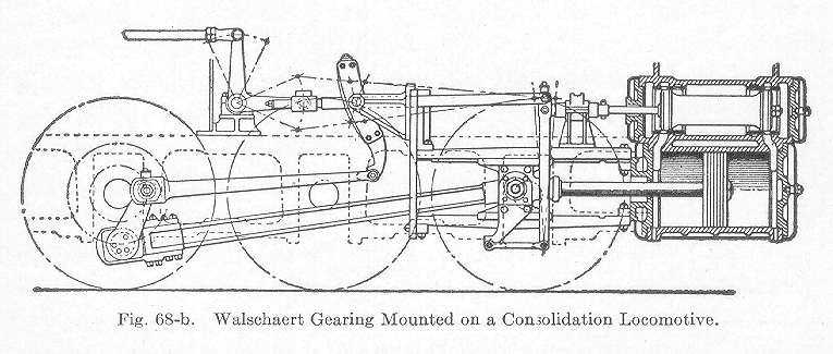
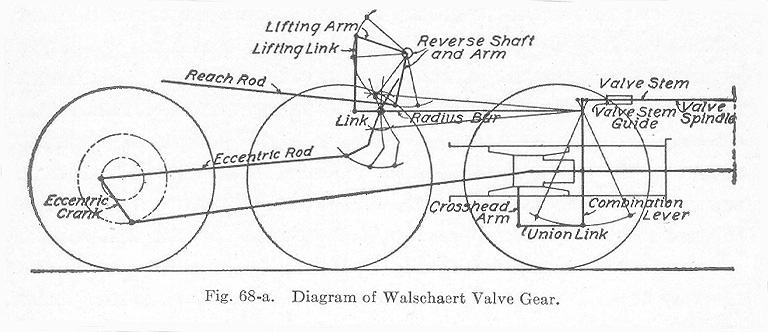
Walschaert Valve Gear. The Walschaert valve gear is illustrated by the line diagram in Fig. 68-a. Fig. 68-b shows its application to a Consolidation freight locomtive. From a study of Fig. 68-a it is obvious that the motion of the valve is obtained from the crosshead and an eccentric crank attached to the main crank pin. In some designs, the eccentric pin is replaced by the usual form of eccentric attached to the main driving axle. The crosshead connection imparts a movement to the valve which in amount equals the lap plus the lead when the crosshead is at the extremities of the stroke, in which position the eccentric crank is in its mid-position. The lead of the valve is constant and can only be changed by altering the leverage relation of the combination lever. The eccentric crank actuates the eccentric rod which, in turn, moves the link to and fro very much the same as does the eccentric blade in the Stephenson gear. There is a radius bar, Fig. 68-a, which connects the link block with the valve stem. It is evident, therefore, that the valve obtains a motion from the eccentric crank, link, radius bar, and valve rod in a manner similar to the Stephenson, the main difference being in the crosshead connection which results in giving the valve a constant lead.It is to be noted that in a valve having internal admission, the radius bar connects with a combination lever above the valve rod connection, as shown in Fig. 68-b, and that in a valve having external admission, the connection is made below the valve rod, as illustrated in Fig. 68-a; also, in a valve having internal admission, the eccentric crank follows the main crank, while in a case where the valve has external admission, it precedes the main crank. Theoretically, the eccentric crank is 90 degrees from the main crank but because of the angularity of the eccentric rod, it is usually two or three degrees more.
The Walschaert gear is operated by a reverse lever in the same manner as the Stephenson gear. In the Stephenson gear, a movement of the reverse lever causes the link to be raised or lowered, the link block remaining stationary, whereas in the Walschaert gear, the link remains stationary and the link block is raised or lowered. From a study of the two gears, it may be stated that the chief point of difference is that the Walschaert gives a constant lead for all cut-offs, whereas the Stephenson gives a different lead for different cut-offs. The following steps given by the American Locomotive Company for adjusting the Walschaert valve gear are presented:
- The motion must be adjusted with the crank on the dead centers by lengthening or shortening the eccentric rod until the link takes such a position as to impart no motion to the valve when the link block is moved from its extreme forward to its extreme backward position. Before these changes in the eccentric are resorted to, the length of the valve stem should be examined, as it may be of advantage to plane off or line under the foot of the link support which might correct the length of both rods, or at least only one of these would need to be changed.
- The difference between the two positions of the valve on the forward and back centers is the lead and lap doubled and it cannot be changed except by changing the leverage relations of the combination lever.
- A given lead determines the lap or a given lap determines the lead, and it must be divided for both ends as desired by lengthening or shortening the valve spindle.
- Within certain limits, this adjustment may be made by shortening or lengthening the radius bar but it is desirable to keep the length of this bar equal to the radius of the link in order to meet the requirements of the first condition.
- The lead may be increased by reducing the lap, and the cut-off point will then be slightly advanced. Increasing the lap introduces the opposite effect on the cut-off. With good judgment, these qualities may be varied to offset other irregularities inherent in transforming rotary into lineal motion.
- Slight variations may be made in the cut-off points as covered by the preceding paragraph but an independent adjustment cannot be made except by shifting the location of the suspension point which is preferably determined by a model.
Table of Contents; Page 85; Page 92; Index
