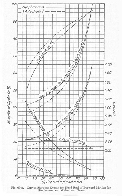
Comparison between Stephenson and Walschaert Gears. A comparison of the Stephenson and Walschaert valve gears shows that steam distribution in former would not differ to a very great extent form that in the latter save in that produced by the constant lead. The factors in favor of the Walschaert gear are largely mechanical ones which may be designated as easily accessible parts and a less amount of care in maintenance. The parts making up the Walschaert valve gear are outside of the frames where they can be easily reached in case of breakdowns and necessary repairs. Another advantage accruing from this fact is that the space between the frames is left open permitting bracing, which protects and strengthens the frames. This is not possible when the Stephenson gear is used. The smaller number of moving parts, hardened pins, and accessible bearings in the Walschaert gear result in fewer and less expensive repairs.A study of the action of a valve on a given locomotive, when operated by means of a Walschaert gear and also a Stephenson gear, gave the results shown graphically in Figs. 69-a and 69-b. The results were taken from Zeuner diagrams, drawn to represent the steam distribution given by each gear. The general dimensions of the two gears, taken from designs prepared for use on a given locomotive are shown in Table VIII.
The conditions for both the head end and crank end of the forward motion, in both Stephenson and Walschaert gears are represented in Figs. 69-a and 69-b. Each event of the cycle-valve travel, port opening, and lead-is plotted with reference to the cut-off. As can be seen, the Walschaert gear gives for all cut-off positions a later admission, later release, later compression, less lead, less port opening, and less valve travel than does the Stephenson gear. With the exception perhaps of lead, the differences are negligibly small for all cut-off positions beyond 50 per cent. With cut-off positions less than 50 per cent, however, these differences increase quite rapidly.
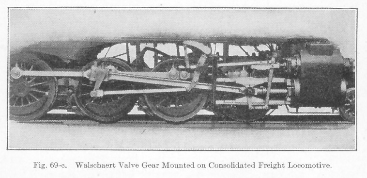
The Walschaert gear is applied to a locomotive in several ways, each having its own advantages. The method illustrated in Fig. 69-c gives the student a general idea how the scheme is worked out and applied in connection with a consolidative freight locomotive.
TABLE VIII
Comparative Dimensions of Stephenson and Walschaert Gears
Stephenson Gear Walschaert Gear Type of valve D-Slide D-Slide Steam lap in inches, H.E. 1.0 1.0 Steam lap in inches, C.E. 1.0 1.0 Exhaust lap in inches, H.E. 0 0 Exhaust lap in inches, C.E. 0 0 Lead at full gear in inches 3/64 3/64 Lead at mid gear in inches 1/4 3/64 Width of port in inches 1 1 Maximum valve travel in inches 6 6 Stroke of piston in inches 24 24 Length of connecting rod in inches 96 96 Radius of link arc in inches 60 Length of radius rod in inches 46
Table of Contents; Page 89; Page 95; Index
