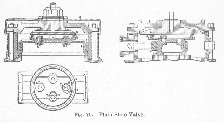
Valves. Until recent years the valve ordinarily used on locomotives was the plain slide valve, partially balanced. In the plain slide valve the full steam chest pressure is exerted over the whole of the back surface of the valve. The balancing of a valve consists in removing a portion of this pressure, thus decreasing the frictional resistance of the valve on its seat. The percentage of this pressure that is removed, or the amount of balance, varies from 45 to 90 per cent of the total face of the valve, and the average in practice is about 65 per cent. In the valve shown in Fig. 70, the balance is 69 per cent. The pinch of the packing ring on the cone slightly increases the pressure of the valve on its seat.In Fig. 70, the valve, 1, is of the ordinary D type driven by the yoke, 2, which is forged as a part of the valve stem. To the back of the valve is bolted a circular plate, 3, having a cone turned thereon. On this cone is fitted a loose ring, 4, the inner face of which is beveled to the same degree as the taper of the cone. The ring is cut at one point and is, therefore, flexible. The open space at the cut in the ring is covered by an L-shaped clip which is placed on the outside and fastened to one end of the ring, the other end of the ring remaining free. This L-shaped clip reaches to the top of the ring at the outside and under the ring at the bottom to the taper of the cone. It thus forms joints just the same as the ring itself, making a continuous yet flexible ring. The ring is made of cast iron and is bored smaller than the diameter required for the working position. Therefore, before the steam chest cover is placed in position, it sets slightly higher on the cone than it does when at work. To the inner side of the steam chest cover, 6, is bolted a back plate, 5, against which the ring, 4, forms a steam tight joint. Owing to the raised position of the ring when first put on, the placing of the cover and the back plate forces the ring down over the cone. This expands the former to a larger diameter and it is thus held in its expanded position under tension with the tendency to maintain the joint between itself and the wearing plate.
Another method employed in balancing a slide valve is to cut grooves in the top of the valve which extend across the four sides of the valve. In these grooves are placed carefully fitted narrow strips which rest on small springs which keep the strips pressed up against a pressure plate, thus keeping the steam away from a large part of the valve.
In order to provide for any leakage which may occur past the ring and to prevent an accumulation of pressure within the same, the holes, 7, are drilled through the studs, 8. These drain the space and accomplish the desired result.
A relief valve is placed on the steam chest. This is a check valve opening inward and serves to equalize the pressure in the two ends of the cylinder when the locomotive is coasting, thus preventing unequal pressure at either end.
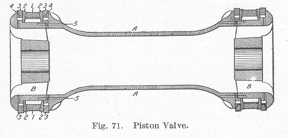
Another form of valve which is now being extensively used is the piston valve, illustrated in Fig. 71. In this valve, the steam is admitted at the center in the space A and. is exhausted at the ends. Such valves are self-balanced since they are entirely surrounded by steam. Another form of piston valve is constructed with a passage extending through its entire length which connects with a live steam passage. In this type of valve, steam is admitted at the ends of the valve at B, and when exhausted passes around the circular part A to the exhaust cavity. In piston valves, it only remains to pack the ends to prevent steam leaks. This is done by using packing rings. In Fig. 71, the packing consists of seven pieces at each end, numbered 1, 2, 3, and 4. Numbers 3 and 4 are the packing rings proper. They consist of the split rings, 3, and the L-shaped covering piece, 4, for the split in No. 3. The rings, 2, are solid and serve merely as surfaces against which the rings, 3, have a bearing. The wedge ring, 1, is split and can expand. The rings, 3, are turned larger than the diameter of the steam chest and are sprung into position. Small holes, 5, are drilled from the steam space A to a point beneath the wedge ring, 1. When the throttle valve is opened, steam enters the holes, 5, forcing the wedge, 1, out between the rings, 2. It locks the packing ring, 3, firmly between the ring, 2, and the lip of the valve. This prevents rattling and working loose of the rings, making the valve practically steam-tight.
A form of packing largely used and which is much simpler than the above, consists of ordinary snap rings inserted into annular grooves cut around the heads of the valves.
Table of Contents; Page 92; Page 98; Index
